Documentation
Controls and input
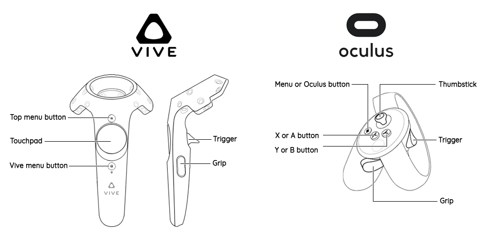
HTC Vive
- Trigger - Used to do the action of the current tool. Is similar to clicking with a mouse.
- Touchpad - This is the ⋮ tools button. Hold it in to choose which tool you want to use. The touchpad is also used to scroll in various tools.
- Grip buttons - Hold in these buttons to move and scale your model.
- Small top button - This is the context menu button. Hold it in to get additional options for the current tool.
- Small bottom button - Is the Steam Home button and will load the Steam Home Page. Can be disabled in SteamVR.
Oculus Rift
- Trigger - Used to do the action of the current tool. Is similar to clicking with a mouse.
- Thumbstick - Used only to scroll.
- Grip button - Hold in these buttons to move and scale your model.
- X or A buttons - This is the ⋮ tools button. Hold it in to choose which tool you want to use.
- Y or B buttons - This is the context menu button. Hold it in to get additional options for the current tool.
- Left menu button - Unassigned.
- Right Oculus button - Default action of loading the Oculus home page.
Tools
Choosing a tool
How to choose the tool you want to use with each controller.
- To choose a tool, hold in the ⋮ tools button, a list of tools will appear in front of the controller, move the controller to the tool you would like to use. The tool's icon will highlight when the controller is over it. Release the ⋮ tools button while you are over the tool to select it. You will see the icon on the controller change to the current tool of that controller.
- Each controller can have only one active tool.
- Each controller has the same list of tools available.
- You can have two different tools on each controller or the same tool on both controllers.
- With some tools, when you start to use that tool, the other controller can be used to help with that action.
- You cannot use two tools simultaneously (but you can use them in succession).
The Context Menu
Each tool has its' own Context Menu, which is a list of additional command or settings for that tool. You can think of it as being similar to a "right click" menu.
- To open the context menu, hold down the Context Menu button, on a Vive this is the small top menu button, on an Oculus Rift this is button Y of B.
- While holding the Context Menu button in move the controller, you will see a small pointer move with your controller.
- Move the pointer over the option you wish to select and then release the Context Menu button to select it.
Navigation tools
Teleport tool
The tool for moving around your model at 1:1 scale.
- Pull in the trigger to aim where you would like to teleport to.
- Release the trigger to teleport to your selected position.
- If the pointer is blue you can teleport, if the pointer is pink you cannot teleport.
- When you teleport the scale is always changed to 1:1.
- You can use the Context Menu to set how far you can teleport.
- When you are not inside the warehouse, there is a small warehouse icon; aim on it to teleport back to the original warehouse view.
- As a shortcut, teleporting straight up (slightly to the back) will also return to the original warehouse view.
- The teleport preview arc will bounce off vertical or slanted surfaces.
- The teleport preview arc can pass through transparent surfaces. If the surface is half-transparent, the arc will pass through if it aims straight through it, but not if it reaches the surface from a shallow angle.
Teleport tool Context Menu options
- short arc - Set the teleport arc to be very small.
- regular arc - Set the teleport arc to its normal length. (default)
- long arc - Set the teleport arc to be very long.
- flat line - Set the teleport arc to be a straight line.
- flip world 90° - Temporally rotate the world by 90°, sometimes it is easier to work like this.
- go to warehouse - Zoom out to the warehouse view.
- go back - Go to previous view position.
- list of scenes... - Open the Settings panel to the Scenes tab.
- turn left - Turn yourself 90° to the left.
- turn right - Turn yourself 90° to the right.
Zoom and Pan
Navigate around your model at any scale. This is not a standard tool; instead, it is always available, using the ↔ grip button.
- Zoom with both controllers. Press in the ↔ grip button on both controllers at the same time, then move the controllers away from each other to zoom in or towards each other to zoom out. You can also rotate the model horizontally in this way.
- Zoom with one controller. Hold in the ↔ grip button on a controller and then scroll on the touchpad/thumbstick to zoom in or out.
- Pan. Press in the ↔ grip button on one controller and move the controller. The model will move with the controller until you release the ↔ grip button.
- When zooming, red text will appear between the two controllers indicating what scale you are at. The scale will snap to certain common scales.
Selection tools
Select tool
The tool to select individual or multiple lines, faces or groups.
- Click select. Move the controller to the geometry you wish to select and pull the trigger to select it. If that geometry is already selected it will deselect it.
- You can move the controller while the trigger is pressed to select or deselect more.
- If you pull the trigger twice quickly, like double clicking, you will select the geometry adjacent the object your controller is touching. If you double-click on an edge that is part of a longer curve, all the edges along that curve are selected.
- If you pull the trigger three times quickly, you will select all the geometry touching the object your controller is touching.
- Box select. While your controller is not touching any geometry pull in the trigger and drag the controller. This will create a selection box and will select anything that is inside the box.
- If you drag from the top down your selection (in blue) will include only the geometry fully inside the box.
- If you drag from the bottom up your selection (in green) will include all the geometry that touches the box.
- The select tool gives you a preview of what will be selected by highlighting the geometry in blue.
- De-select everything: With the select tool active, click on nothing to de-select any current selections, or use the Context Menu button
- De-select individual things: With the select tool active, click on any currently selected geometry to de-select it. There is a pink preview highlighting what will be de-selected.
Laser-select tool
The tool to select individual or multiple faces or groups from a distance.
- Aim the laser at the geometry you wish to select, click with the trigger to add it to your selection. If that geometry is already selected it will deselect it.
- The laser-select tool cannot be used to select or de-select individual edges---you can only point to faces or groups. However, you can select all the edges adjacent to a face by pulling the trigger twice quickly, like double clicking. There is also a Context Menu tool to do this.
- If you pull the trigger three times quickly, you will select all the geometry connected to the face. There is also a Context Menu tool to do this.
- The laser-select tool gives you a preview of what will be selected by highlighting the geometry in blue. You can move your hand while holding down the trigger to select more things.
- De-select everything: With the laser-select or normal select tool active, click on nothing to de-select any current selections. There is also a Context Menu tool to do this.
- De-select individual things: With the laser-select or normal select tool active, click on any currently selected geometry to de-select it. There is a pink preview highlighting what will be de-selected.
Select and Laser-select tool Context Menu options
- Make group - Turns the currently selected geometry into a new group.
- Make component - Turns the currently selected geometry into a new component.
- Deselect all - De-selects everything that you had selected.
- Select nearby edges and faces - Selects all edges and faces touching the current selection. Similar to the double click selection.
- Select all connected - Selects all edges and faces connected the current selection. Similar to the triple click selection.
- Open group/component - Opens the currently selected group or component. (only visible if a group or component is selected)
- Exit group/component - Closes the group or component that you currently have open. (only visible if a group or component is selected)
- Close all levels - Close all groups you have open.
- Explode - Splits the selected group or component up into its geometry. (only visible if a group or component is selected)
- Intersect - This computes the intersection of the selected face (or faces) with the rest of the model, and adds it as extra edges. If you have selected several faces or groups and there is an intersection between them, then this is the intersection that will be computed, and the rest of the model is ignored.
Groups and Components
How to work with Groups and Components.
Entering a Group or Component
- Use the select or laser-select tool to double click on any Group or Component to open it.
- Or with the Group or Component selected, press in the Context Menu button and choose the Open Group tool.
- When inside a Group or Component the rest of the model changes colour and cannot be edited; or it might disappear from view altogether. (This can be changed in the Rendering settings in VR, or the standard SketchUp option "View, Component Edit, Hide Rest Of Model".)
Exiting a Group or Component
- While inside a Group or Component, use the select or laser-select tool and double click outside of the Group or Component to exit.
- Or while inside a Group or Component, press in the Context Menu button and choose the Exit Group tool to exit the current Group or Component.
Creating Group or Component
- Use the select tool to select the geometry you wish to group. Then press in the Context Menu button and choose either the Make Group tool or the Make Component tool.
Converting groups into Components
- Use the select tool to select the Group you wish to convert, then press in the Context Menu button and choose Turn Group into Component tool.
Exploding Groups or Components
- Use the select tool to select the Group or Component, then press in the Context Menu button and choose Explode tool to un-group the Group or Component.
Axis Tool
The tool to re-position and re-align the axis of a group or component.
- Set axis position: With the Axis tool selected move the axis indicator to the position you want and then click the trigger to set the position.
- Set axis rotation: With the Axis tool selected hover over one of the extended axis lines (blue, red or green) then use the trigger to click on the line and drag it to a new rotation.
Drawing tools
Erase or Hide tool
How to delete or hide geometry.
Erase
- Move the controller over the object you wish to erase and pull the trigger.
- With the Erase tool active, as you move the controller a red highlight will indicate what will be deleted if you where to pull the trigger.
- To delete more than one object per click, use the select tool to select what you want to delete then use the Erase tool to delete that selection.
- Or, with the Erase tool active, hold the trigger pressed and move over several objects.
Hide
- With the Erase tool selected use the Context Menu button to turn on the "Hide Mode" option.
- Now you can use the tool exactly the same way as when you are erasing except you are only hiding the geometry, not deleting it.
- To un-hide geometry, use the Context Menu button and select the "Unhide all" option.
Erase or Hide tool Context Menu options
- Hide mode - Changes the Erase tool into the Hide tool when it is selected.
- Unhide all - Shows all hidden geometry.
Line tool
How to draw a line between two points.
- Click one with the trigger to start drawing the line. Move the controller then click a second time to finish the line.
- It is also possible to start drawing the line by pulling in the trigger and holding it in and only releasing it when you want to finish the line.
- You can cancel drawing a line by pressing the ⋮ tools button, which is highlighted red while drawing a line.
- After drawing a line, if the end point is not a pre-existing point, then it is automatically chosen as the start point of the next line. If you do not want to draw more lines, use cancel as described above.
Line tool Context Menu options
- Lock direction to... - Locks the direction of the line to an axis or plain.
- Unlock direction - Unlocks the line so it can point in any direction. This option only shows if the line is locked.
- Set length - Opens the calculator input panel where you can set the length of the line you wish to draw.
Arc tool
How to draw an arc with 3 points of control.
- Drawing an arc is similar to drawing a line. Set the start point of the arc by clicking the trigger, move the controller to set the length and click a second time to mark the end point of the arc. Move the controller again to position the third point which the arc will pass through. Pull the trigger a third time to complete the arc.
- While drawing an arc (after setting the start point) you can choose the number of segments the arc will be divided into pressing the Context Menu button and selecting the number of segments you wish.
Arc tool Context Menu options
- Number of segments - Sets the number of segments that the arc will be divided into
- Set length - Opens the calculator input panel where you can set the length of the arc you wish to draw.
- set bulge - Opens the calculator input panel where you can set the length of the bulge of the arc.
Freehand tool
The tool for freehand sketching.
- Either click the trigger once or hold it in to start drawing the line. Click a second time or just release the trigger to end the line.
- The first and last point follow the normal snapping rules, but the rest of the freehand line mostly does not snap to any axis, plane or object. The exception is that it snaps to faces that contain the first point.
Rectangle tool
The tool for drawing rectangles.
- Either click the trigger once or hold it in to start drawing the rectangle. Click a second time or just release the trigger to end the rectangle.
- The rectangle is oriented so that one side always follows one of the axes. To do a slanted rectangle, you may have to change which axis is followed. To do that, squeeze the rectangle along this axis, then move back.
- While drawing a rectangle with one controller you can use the other to lock an axis or set a length manually. See the section on Setting lengths and Locking for more information.
Rectangle tool Context Menu options
- Lock direction to... - Locks the direction to an axis or plain.
- Unlock direction - Removes any locking constraints. This option only shows if the direction is locked.
- Set length - Opens the calculator input panel where you can set the length of rectangle.
- set width - Opens the calculator input panel where you can set the width of rectangle.
Box tool
The tool for drawing boxes.
- Either click the trigger once or hold it in to start drawing the box. Click a second time or just release the trigger to end the box.
- The box is always axis-aligned.
- You can set the width, length and height of the box manually. See the section on Setting lengths for more information.
Polygon tool
The tool for drawing polygons with any number of sides. Very similar to the circle tool.
- Either click the trigger once or hold it in to set the center point of the polygon. Move the controller away and click a second time or just release the trigger to set the radius and complete the polygon.
- The polygon can be drawn inside one of the axis planes, or, if the center touches one or more existing faces, it can be drawn inside the planes of these faces.
- While drawing a polygon (after setting the center point) you can choose the number of segments the polygon will have by using the Context Menu button.
Polygon tool Context Menu options
- Number of segments - Sets the number of segments that the polygon will be divided into.
- Set radius - Opens the calculator input panel where you can set the radius of polygon.
- Circumscribed - Choose if the radius should be measured to the center point of the edges or the vertexes of the polygon.
Circle tool
The tool for drawing circles. Very similar to the polygon tool.
- Either click the trigger once or hold it in to set the center point of the circle. Move the controller away and click a second time or just release the trigger to set the radius and complete the circle.
- The circle can be drawn inside one of the axis planes, or, if the center touches one or more existing faces, it can be drawn inside the planes of these faces.
- While drawing a circle (after setting the center point) you can choose the number of segments the "circle" will be made of by using the Context Menu button.
Circle tool Context Menu options
- Number of segments - Sets the number of segments that the circle will be divided into.
- Set radius - Opens the calculator input panel where you can set the radius of circle.
Editing tools
Push-Pull tool
The tool to extrude out perpendicular a face to create depth.
- Move the controller until it is intersecting with a face. The face will highlight green to indicate which face will be affected. Click once with the trigger on the face to start pulling it. Move the controller the desired distance and then either click a second time or release the trigger to finish.
Push-Pull tool Context Menu options
- Set distance - Opens the calculator input panel where you can set the distance of the push or pull.
- Create new stating face - If this is selected then then when you push or pull a face, the original face remains and a new face is pushed or pulled instead.
Extrude tool / Follow Path
The tool to extrude out faces or edges in any direction or along a path. Similar to the Push-Pull tool but not limited to only pulling one face perpendicularly.
- Move the controller until it is intersecting with a face or an edge. Click once with the trigger on the face or edge to start extruding it. Move the controller the desired distance and then either click a second time or release the trigger to finish.
- Unlike the Push-Pull tool, the extrude tool can extrude lines. Select some lines (and/or faces) with the select tool, then change to the extrude tool and use it in the same way you would extrude a face, by clicking on the selected lines, moving the controller and clicking again to end the extrusion.
- Extruding in Follow Path mode: After you have clicked once, some nearby lines will be drawn in orange. Move the controller over one of these to enter the Follow Path mode. In this mode you can extend the path (always drawn in orange) to any number of contiguous lines. Move the controller to follow the path you want, step by step.
Extrude tool Context Menu options
- Set distance - Opens the calculator input panel where you can set the distance of the extrude.
- Lock direction to... - Locks the direction to an axis or plain.
- Unlock direction - Removes any locking constraints. This option only shows if the direction is locked.
Offset tool
The tool to offset lines on a face.
- Offset a face. Move the controller until the face you wish to offset is highlighted in green, then either click once with the trigger or hold it in. Move the controller to the desired position and either click a second time or release the trigger to complete the offset.
- Offset lines. Use the select tool to select the lines you wish to offset. Then use the Offset tool in the same way as you would when offsetting from a face. This requires more than one line to be selected.
Offset tool Context Menu options
- Set distance - Opens the calculator input panel where you can set the distance of the offset.
Move tool
How to move and copy objects.
- Move. Move the controller over the object you wish to move. It will highlight purple. Then either click once with the trigger or hold it in, move the controller to the desired position and then either click a second time or release the trigger to complete the move.
- If you want to move more that one thing at a time, use the select tool to select them first then use the move tool.
- Copy. To copy an item, start moving it and then scroll up on the touchpad/thumbstick to set the number of copies to 1. Now when you complete the move action it will create a copy instead of moving the first object.
- Copy multiple. To create multiple copies, start moving an item, and then scroll up on the touchpad/thumbstick to set the number of copies. The new multiple copies will be placed at the same interval as the initial move length.
- Distribute multiple copies. When coping an item if you scroll down on the touchpad/thumbstick to set the number of copies the copies will be distributed equally along the length of the move.
- Freehand movement: In normal usage this tool only allows translations but not rotations. However, if you highlight a group, you will see additional circles drawn on the border of the box. Click inside one of these circles to "grab" the group with the controller. Then the group can be moved and rotated around. There are some custom snapping rules in this mode: the eigth corners of the group will try to snap to existing faces if they are close.
Move tool Context Menu options
- Number of copies - Select the number of copies you wish to make. (Only shows if the "Copy" option is selected)
- Divide distance into steps - If this is selected then the copies will be spread-out evenly along the distance of the copy rather then the default of multiplying the copies out in front. (Only shows if the "Copy" option is selected)
- Copy - Create a copy of the selected geometry.
- Move - Move the selected geometry.
- Set distance - Opens the calculator input panel where you can set the distance of the move.
- Lock direction to... - Locks the direction to an axis or plain.
- Unlock direction - Removes any locking constraints. This option only shows if the direction is locked.
Rotate tool
The tool to rotate objects.
- Move the controller over the thing you wish to rotate. It will highlight purple. Click once with the trigger to set the point around which the object will rotate, move the controller away a little to create a leaver and click a second time. Now move the controller to set the rotation you wish and pull the trigger a third time to complete the rotation.
- A circular ruler is shown to tell you in which plane the rotation occurs. If you move the controller outside the ruler, the angle is unconstrained. If you move the controller inside the ruler, the angle is constrained to multiples of either 5 or 15 degrees. The ruler has got dashes on its edge: short ones every 5 degrees and longer ones every 15 degrees. Move the controller near these dashes for 5-degrees snapping. Move the controller farther inside the ruler for 15-degrees snapping.
- Like the Move tool you can create one or multiple copies when rotating. While rotating, scroll up or down on the touchpad/thumbstick to set the number of copies you wish to make. It you scroll up the copies will be spaced at regular intervals based the the rotation you choose. If you scroll down the copies with be equally distributed along the rotation you choose.
Rotate tool Context Menu options
- Number of copies - Select the number of copies you wish to make. (Only shows if the "Copy" option is selected)
- Divide angle into steps - If this is selected then the copies will be spread-out evenly along the angle of the copy rather then the default of multiplying the copies out. (Only shows if the "Copy" option is selected)
- Copy - Create a copy of the selected geometry.
- Rotate without copy - Rotate the selected geometry.
Scale tool
The tool to scale objects.
- Move the controller to highlight the object you wish to scale. It will highlight green. Pull the trigger to bring up the scale axis handles (green cubes). Move the controller to a handle to select the axis you want to scale the object by. Pull the trigger a second time to start scaling the object. Pull the trigger a third time to finish the scale command.
- To change the scaling center, click on another handle with the other controller.
- The tool can apply distortion. When it does, a purple line is shown. If you want to avoid distortion, keep the controller over this purple line.
Other tools
Paint tool
The tool to choose and place colours and textures on the model.
- Choose a material. Hold in the ⋮ tools button and move the controller over the paint bucket, then move the controller to the right to select a material from the palette and release the ⋮ tools button to choose that material.
- Placing a material. With a material selected aim the laser at the face you wish to paint and click with the trigger.
- Eye-drop a material. With the paint tool selected move the controller to touch the face with the material you want. You will see the tool icon will change to a bucket with a red arrow pointing into the bucket. Click with the trigger to make the material of the face become your currently selected material.
Paint tool Context Menu options
- Sample material - Select the material you pointing at and set it to the current tool. Works like an eye-dropper tool.
- Add "Material" to quick palette - Adds the selected material to the quick selection palette.
Materials
The tool where you can select, edit and create new materials.
- Enter the material menu. Hold in the ⋮ tools button and move the controller over the materials icon and then release the button. This will display the materials menu.
- Select a material. While inside the materials menu, click on the vertical bar on the left to access the full materials menu. Use the trigger to click on the material you want. Press the ⋮ tools button to leave the materials menu.
- You can add more materials to your quick-access palette by clicking on each of them with the trigger.
- The quick-access palette is just a list of the most recently used materials. You can reorganize this list by dragging materials around or out of the quick-access palette.
- Edit a material: You can edit the currently selected material with the controls on the right.
- In the colour bowl you can drag the control point by moving the controller over the point and holding in the trigger and moving the controller. You will see the preview cube update. Moving the point around the circle changes its hue and saturation while moving the point up and down adjusts its value.
- You can adjust the amount for red, blue, green and transparency of the material by using the trigger to drag the sliders left or right. You will see the preview cube update.
- As common for SketchUp, if you change the color of a material, it affects anything in your model that is currently using this material. Use the "Duplicate" icon if you want to first make a copy.
- To exit the material menu, press the ⋮ tools button.
History tool
The tool to undo or redo any action.
- To undo an action, hold down the ⋮ tools button, move the controller over the red arrow icon, and then release the ⋮ tools button.
- When you move the controller over the red action arrow icon, more actions appear below it. Lower icons correspond to older actions. If you select a lower icon, all actions up to that one are undone.
- To redo an action that you have just undone, hold down the ⋮ tools button, move the controller over the green arrow icon and then release the ⋮ tools button.
- The redo arrow icon only shows if you have just used the Undo tool. If you have undone more than one step, you can also redo more than one step at once.
Tool Extras
Canceling any action
How to end or stop doing an action.
- To end an action you don't want to finish, press the ⋮ tools button. This button is shown in red when clicking it will cancel an action in progress.
Setting lengths
- When dragging out a length like when using the Line or Push/Pull tools, the length snaps to logical increments depending on the current scale. If you are zoomed out the length might snap to the nearest meter. If you are zoomed in the length might snap to the nearest mm.
- Whenever the length measurement is visible it is possible to manually input a precise length: choose "set length" or a variation in the Context menu, or directly click on the numbers with the other controller. For example if you start drawing a line with your right controller, you can use the left controller to click on the measurement text. A small calculator window will appear where you can use the trigger to input any length you wish the line to be.
Snapping
- Axis snapping. Many actions like drawing a line or rectangle automatically snap to the x,y,z axis. The guidelines change colour (red, green and blue) to match the axis currently snapped to.
- Plane snapping. Many actions also snap to the x,y,z planes. This is indicated by a small coloured square at the controller's tip. The square changes colour to match the plane it is snapping to.
- Point snapping. Many actions snap to the nearest existing point, line, midpoint of a line or face.
- The distance at which snapping starts to happen can be set in the configurations menu.
- If you have trouble picking the point you want, try this:
- Zoom in. This will make the points farther apart, and easier to pick. It is expected that with a little bit of practice you should constantly be zooming in and out when editing.
- Move the touchpad/thumbstick left or right. This will temporarily reduce the snapping distance.
Locking
- Locking an axis or plane. Many actions like drawing a line or rectangle can have their axis locked. This is done by using the controller not doing the action to click on the length indicator line or plane indicator guideline or by using that tool's Context Menu.
- When locking is available an icon of a lock will appear on the length indicator line.
- To unlock a locked axis or plane, pull the trigger of the controller not doing the main action.
- The rectangle tool has got more advanced locking rules: you can lock any edge of the rectangle being drawn, which fixes this edge's direction and length. It is possible to draw a rectangle which is not aligned to any axis, by locking an edge and moving the other, possibly several times.
Guidelines
- When drawing, guidelines and reference points (white spheres, also called input points) will appear and mark what points the current action is snapping to.
- When drawing with one controller you can move the other controller over a point to create a reference point and guideline that the first controller can snap to.
- You can also use a single-controller movement: move over a point to create a reference point, and then move back to where you want to be (similar to SketchUp with the mouse).
Dynamic Components
- VR Sketch supports animating SketchUp's dynamic components.
- To interact with a dynamic component, use the Teleport tool touch the component. A light blue box will appear to indicate that the component is interactable. While touching the component pull the trigger and move the controller. (This requires VR Sketch 11 or newer.)
- You can also aim the teleporter beam towards an interactable component. When you let go of the trigger, the component animates, like with the Interact tool of SketchUp.
- Currently we only support dynamic components that make use of one of the
ANIMATE...()functions and that directly set the position (X, Y, Z) or the rotation (RotX, RotY, RotZ). If these functions are used to set a custom variable instead, the animation will not be recognized by VR Sketch. Please let us know if you need more cases. - There is a separate Interact tool in VR Sketch, which you can use to view and move interactable components, as well as edit animations (with the Context Menu button).